Comparison of Partial Admission Axial and Radial Inflow Turbines for Underwater S-CO2 Power Cycle System
-
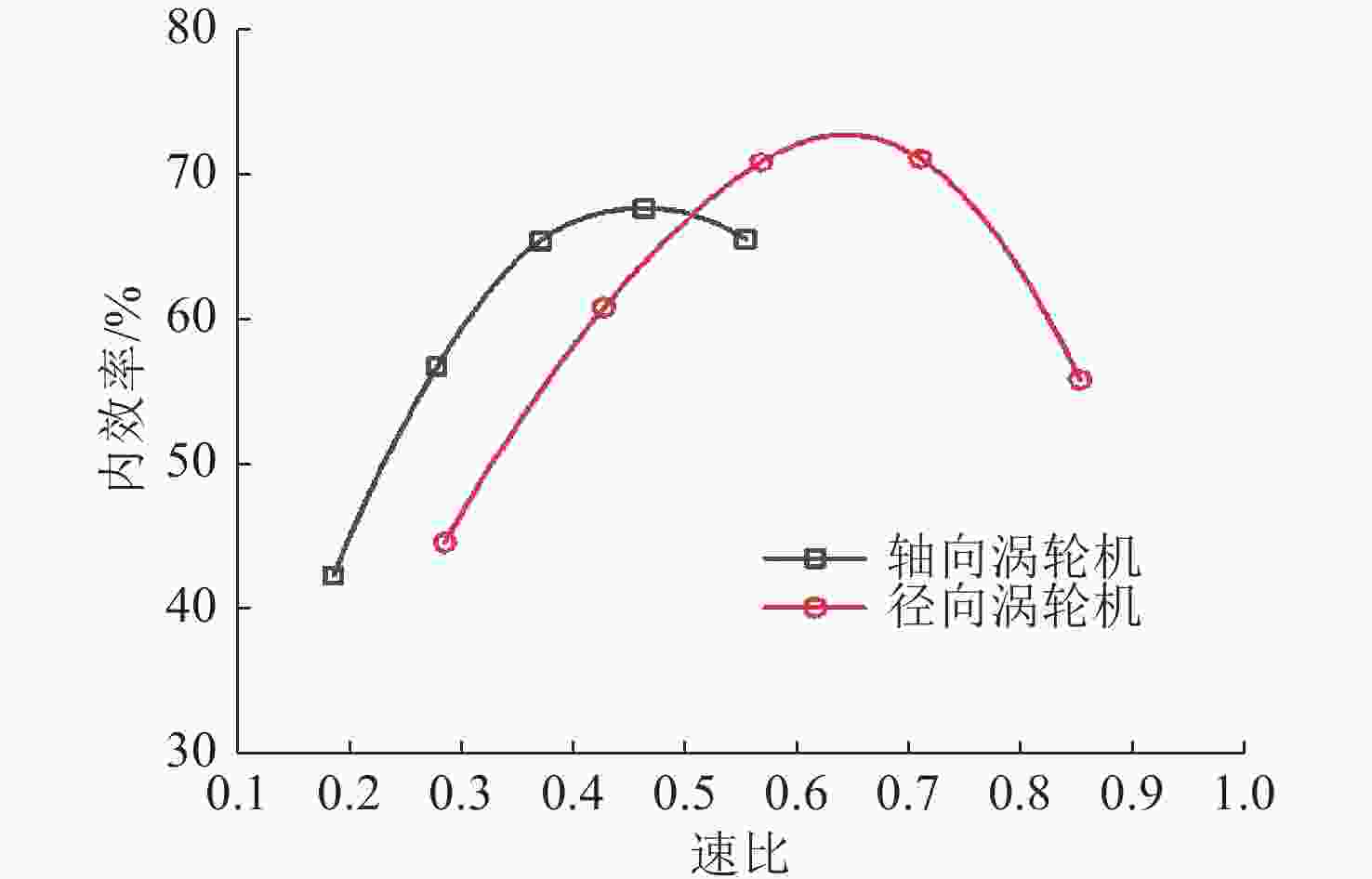
摘要: 将超临界二氧化碳(S-CO2)循环动力系统合理应用于无人水下航行器(UUV), 有助于解决现有 UUV 蒸汽动力循环系统尤其是针对小功率等级应用效率低的问题。为合理选型水下 S-CO2系统涡轮机, 结合损失模型的一维方法获得了设计空间内的最佳几何参数, 并基于 RANS 方程的三维数值仿真方法验证了一维设计方法的合理性, 进一步对比分析了轴/径向涡轮机的气动性能及流动特性。结果表明, 设计工况下径向涡轮机内效率比轴向涡轮机高5.41%, 但尺寸较大, 约为轴向涡轮机的2倍; 径向涡轮机的主要损失集中在喷管和转子非工作段, 而轴向涡轮机则主要为转子处产生的二次流损失。通过变工况分析发现, 轴向涡轮机更适用于低速比工况, 但在同一转速下径向涡轮机效率更高。文中研究结果可为应用于UUV的S-CO2系统动力主机的研制提供参考。Abstract: The reasonable application of supercritical carbon dioxide(S-CO2) power cycle systems to unmanned undersea vehicles(UUVs) can help address the problem of low efficiency for the existing UUV steam power cycle systems, especially for small-power applications. In order to select the optimal turbine for the underwater S-CO2 system, the one-dimensional approach combined with the loss model was used to obtain the best geometric parameters within the design space. In addition, the three-dimensional numerical simulation method based on the RANS equation was adopted to verify the rationality of the one-dimensional design method. The aerodynamic performance and flow characteristics of the axial/radial turbine were further compared. The results show that the internal efficiency of the radial turbine is 5.41% higher than that of the axial turbine under the design conditions, but the size of the radial turbine is larger, about twice that of the axial turbine. The main loss of the radial turbine is from the nozzle and the rotor non-working section, while that of the axial turbine is mainly concentrated in the secondary flow losses generated at the rotor. Through the analysis of variable operating conditions, it is found that the axial turbine is more suitable for the low velocity ratio operating conditions. Nevertheless, the radial turbine has higher efficiency at the same speed. This research can provide a reference for the development of the S-CO2 system power unit applied in UUVs.
-
表 1 用于模型验证的涡轮机几何尺寸
Table 1. Turbine geometric dimensions used for model validation
径向涡轮机 轴向涡轮机 参数 数值 参数 数值 喷管入口半径/mm 74.00 中径/mm 25.76 喷管出口半径/mm 63.50 叶片高度/mm 1.52 转子入口半径/mm 58.20 中径/mm 25.76 转子出口轮毂半径/mm 15.20 喷管数 5.00 转子入口叶顶角度/(°) 0.46 喷管斜切角/(°) 15.00 转子出口叶顶角度/(°) 61.47 叶片安装角/(°) 25.00 喷管数 19.00 叶片高度/mm 1.52 喷管弦长/mm 22.90 转子数 75.00 喷管叶片高度/mm 6.18 叶片弦长/mm 1.88 转子入口叶片高度/mm 6.35 叶片边缘厚/mm 0.08 转子出口叶顶半径/mm 36.80 喉部直径/mm 0.56 转子入口轮毂角度/(°) 0.04 喷管出口直径/mm 1.27 转子出口轮毂角度/(°) 39.40 转子数 75.00 转子数 16.00 叶片弦长/mm 1.88 表 2 模型验证所选边界条件
Table 2. Boundary conditions selected for model validation
径向涡轮机 轴向涡轮机 边界条件 数值 边界条件 数值 转速/(r/min) 71 700 转速/(r/min) 435 000 入口总压/MPa 0.413 入口总压/MPa 2.068 入口总温/K 477.6 入口总温/K 1 255 出口静压/MPa 0.072 4 出口静压/MPa 0.034 5 表 3 网格无关性验证
Table 3. Verification of mesh independent
节点数 径向涡轮机内效率/% 轴向涡轮机内效率 /% 1.5×10⁶ 85.45 61.25 2.0×10⁶ 85.53 61.39 2.5×10⁶ 85.52 61.38 表 4 不同算法与试验结果对比
Table 4. Comparison of different methods and experimental results
算法 径向涡轮机内效率/% 轴向涡轮机内效率/% 一维计算 86.3 60.04 仿真计算 85.50 61.40 试验 86.40 62.90 表 5 涡轮机设计参数
Table 5. Turbine design parameters
参数 数值 转速/(r/min) ≤100 000 入口总压/MPa 18 入口总温/MPa 873 出口静压/MPa 7.96 功率/kW 30.61 喉部直径(宽度)/mm ≥1 表 6 径向和轴向涡轮机所选设计点尺寸参数
Table 6. Geometry parameter of selected radial and axial turbines
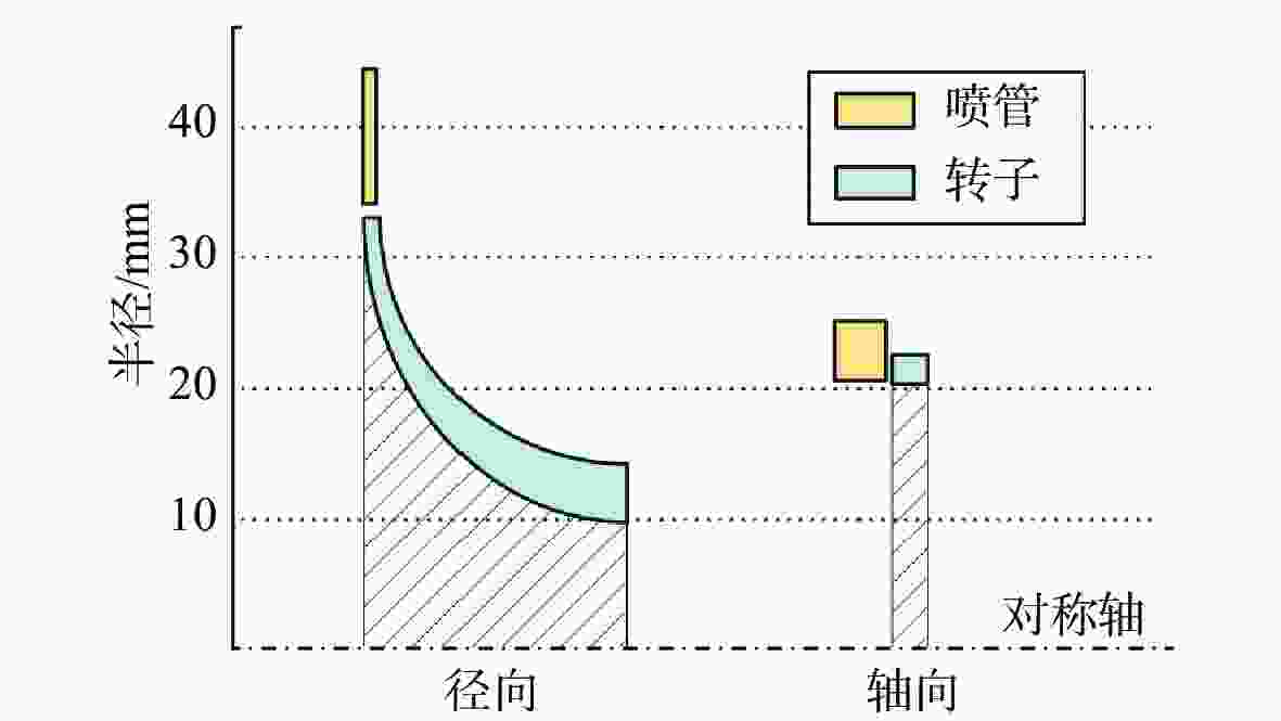
径向涡轮机 轴向涡轮机 参数 数值 参数 数值 喷管入口半径/mm 44.36 中径/mm 42.91 喷管出口半径/mm 34.00 叶片高度/mm 2.20 转子入口半径/mm 32.99 叶片安装角/(°) 24.99 转子出口轮毂半径/mm 9.80 喷管数 5.00 转子入口角度/(°) 28.80 部分进气度 0.26 转子出口叶顶角度/(°) 63.90 转子数 77.00 喷管数 9.00 叶片弦长/mm 2.72 部分进气度 0.43 叶片边缘厚度/mm 0.11 喷管喉部宽度/mm 1.37 喉部直径/mm 1.80 喷管叶片高度/mm 1.02 内效率/% 68.52 转子入口叶片高度/mm 1.22 转子出口叶顶半径/mm 14.25 最小叶片边缘厚度/mm 0.50 转子出口轮毂角度/(°) 56.30 转子数 19.00 内效率/% 71.39 表 7 一维计算与仿真计算结果对比
Table 7. Comparison of one-dimensional calculation and simulation calculation results
算法 径向涡轮机内效率 /% 轴向涡轮机内效率 /% 一维计算 71.39 68.52 仿真计算 70.77 65.36 表 8 损失分解方法
Table 8. Loss breakdown method
损失类型 计算方法 计算设置 叶型损失 面平均熵增(从喷管/转子的入口到出口) 全周, 无间隙, 自由壁面 端面损失 面平均熵增(从喷管/转子的入口到出口) 全周, 无间隙, 自由/无滑移壁面 叶顶间隙损失 效率变化 全周, 有/无间隙, 无滑移壁面 出口能量损失 面平均速度(转子出口) 全周, 有间隙, 无滑移壁面 部分进气损失 效率变化 全周/部分进气, 有间隙, 无滑移壁面 -
[1] Wang X, Shang J, Luo Z, et al. Reviews of power systems and environmental energy conversion for unmanned underwater vehicles[J]. Renewable and Sustainable Energy Reviews, 2012, 16(4): 1958-1970. doi: 10.1016/j.rser.2011.12.016 [2] Eagle W, Waters D, Cadou C. System modeling of a novel aluminum fueled UUV power system[C]//Proceedings of the 50th AIAA Aerospace Sciences Meeting including the New Horizons Forum and Aerospace Exposition. Nashville, Tennessee, USA: AIAA, 2000. [3] Harper A D. Thermochemical power systems for underwater applications[C]//Proceedings of the 6th International Symposium on Unmanned Untethered Submersible Technology. Durham, USA: IEEE, 1989. [4] Ahn Y, Bae S J, Kim M, et al. Review of supercritical CO2 power cycle technology and current status of research and development[J]. Nuclear Engineering and Technology, 2015, 47(6): 647-661. doi: 10.1016/j.net.2015.06.009 [5] Hughes T G, Smith R B, Kiely D H. Stored chemical energy propulsion system for underwater applications[J]. Journal of Energy, 1983, 7(2): 128-133. doi: 10.2514/3.62644 [6] Kiely D H, Moore J T. Hydrocarbon fueled UUV power systems[C]//Proceedings of the 2002 Workshop on Autonomous Underwater Vehicles. San Antonio, USA: IEEE, 2002: 121-128. [7] Miller T F, Walter J L, Kiely D H. A next-generation AUV energy system based on aluminum-seawater combustion[C]//Proceedings of the 2002 Workshop on Autonomous Underwater Vehicles. San Antonio, USA: IEEE, 2002: 111-119. [8] Qin K, Wang H, Qi J, et al. Aerodynamic design and experimental validation of high pressure ratio partial admission axial impulse turbines for unmanned underwater vehicles[J]. Energy, 2022, 239: 122242. doi: 10.1016/j.energy.2021.122242 [9] 伊进宝, 赵卫兵, 师海潮. 动叶围带对鱼雷涡轮机通流性能影响研究[J]. 水下无人系统学报, 2012, 20(1): 56-59.Yi Jinbao, Zhao Weibing, Shi Haichao. Effect of rotor shroud on flow passage performance of torpedo turbine[J]. Journal of Unmanned Undersea Systems, 2012, 20(1): 56-59. [10] 郭庆, 罗凯, 党建军, 等. 基于乏汽增压的水下半闭式循环动力系统研究[J]. 水下无人系统学报, 2021, 29(6): 680-689.Guo Qing, Luo Kai, Dang Jianjun, et al. Architecture of underwater semi-closed cycle power system based on exhaust booster[J]. Journal of Unmanned Undersea Systems, 2021, 29(6): 680-689. [11] Holaind N, Bianchi G, De Miol M, et al. Design of radial turbomachinery for supercritical CO2 systems using theoretical and numerical CFD methodologies[J]. Energy Procedia, 2017, 123: 313-320. doi: 10.1016/j.egypro.2017.07.256 [12] Saeed M, Berrouk A S, Burhani B M, et al. Turbine design and optimization for a supercritical CO2 cycle using a multifaceted approach based on deep neural network[J]. Energies, 2021, 14(22): 1-27. doi: 10.3390/en14227807 [13] Grönman A, Uusitalo A. Analysis of radial-outflow turbine design for supercritical CO2 and comparison to radial-inflow turbines[J]. Energy Conversion and Management, 2022, 252: 115089. doi: 10.1016/j.enconman.2021.115089 [14] 王雨琦, 张荻, 谢永慧. 部分进气超临界二氧化碳透平非定常流动研究[J]. 热力透平, 2018, 47(1): 47-52.Wang Yuqi, Zhang Di, Xie Yonghui. Investigation on unsteady flow of a partial-admission supercritical carbon dioxide turbine[J]. Thermal Turbine, 2018, 47(1): 47-52. [15] 周奥铮, 宋健, 任晓栋, 等. 超临界二氧化碳布雷顿循环及其向心透平的设计与分析[J]. 工程热物理学报, 2019, 40(6): 1233-1239.Zhou Aozheng, Song Jian, Ren Xiaodong, et al. The study and analysis of supercritical carbon dioxide brayton cycle and its radial inflow turbine[J]. Journal of Engineering Thermophysics, 2019, 40(6): 1233-1239. [16] 赵攀, 温玉聪, 娄聚伟, 等. 超临界二氧化碳向心透平设计与热流固耦合研究[J]. 西安交通大学学报, 2022, 56(11): 83-94.Zhao Pan, Wen Yucong, Lou Juwei, et al. Design and thermal-fluid-solid coupling investigation of supercritical carbon dioxide radial inflow turbine[J]. Journal of Xi’an Jiaotong Univercity, 2022, 56(11): 83-94. [17] Baines N C, Whitfield A. Design of radial turbomachines[M]. Essex, UK: Longman Scientific and Technical, 1990. [18] Persky R, Sauret E. Loss models for on and off-design performance of radial inflow turbomachinery[J]. Applied Thermal Engineering, 2019, 150: 1066-1077. doi: 10.1016/j.applthermaleng.2019.01.042 [19] Aungier R H. Turbine aerodynamics: axial-flow and radial-inflow turbine design and analysis[M]. New York, USA: ASME Press, 2006. [20] Ohlsson G O. Partial-admission turbines[J]. Journal of the Aerospace Sciences, 1962, 29(9): 1017-1023. doi: 10.2514/8.9686 [21] Zhang J, Qin K, Li D, et al. Potential of organic rankine cycles for unmanned underwater vehicles[J]. Energy, 2020, 192: 116559. doi: 10.1016/j.energy.2019.116559 [22] 查志武, 史小锋, 钱忠博. 鱼雷热动力技术[M]. 北京: 国防工业出版社, 2006. [23] Cao X, Bian J. Supersonic separation technology for natural gas processing: A review[J]. Chemical Engineering and Processing-Process Intensification, 2019, 136: 138-151. doi: 10.1016/j.cep.2019.01.007 [24] Jones A C. Design and test of a small, high pressure ratio radial turbine[J]. Journal of Turbomachinery, 1996, 118(2): 362-370. doi: 10.1115/1.2836651 [25] Ventura C A M, Jacobs P A, Rowlands A S, et al. Preliminary design and performance estimation of radial inflow turbines: An automated approach[J]. Journal of Fluids Engineering, 2012, 134(3): 031102. doi: 10.1115/1.4006174 [26] Wheeler A P S, Ong J. A study of the three-dimensional unsteady real-gas flows within a transonic ORC turbine[C]//Proceedings of the ASME Turbo Expo 2014: Turbine Technical Conference and Exposition. Düsseldorf, Germany: ASME, 2014. -


 下载:
下载:
