Simulation of Torpedo Combustion Chamber Thermal-Fluid-Solid Coupling Heat Transfer
-
摘要: 为了提高鱼雷燃烧室的冷却换热性能, 文中基于热流固耦合数值计算方法, 开展了鱼雷燃烧室内气-液-固三相冷却换热过程数值仿真, 得到了燃烧室在2种不同冷却水流道结构下的流场分布情况, 并对不同流道结构下的冷却换热性能进行了分析。研究结果表明, 随着冷却区域底部流道数量的增加, 冷却区域底部湍流强度减弱, 局部高温区变小; 随着冷却区域出口流道数量的增加, 出口处的湍流、漩涡及局部高温区逐渐消失, 冷却区域底部由水流对冲而产生的截流现象消失; 增加流道数量的方式使换热效率提升, 且增加底部流道数量的方式对换热效率的提升效果更明显; 通过增加燃烧室流道数量使冷却换热功率提升了约8.5%, 壳体的最高温度降低了11 K。文中的研究结果可对鱼雷燃烧室冷却结构的设计及改进提供参考。Abstract: To improve the cooling heat transfer performance of torpedo combustion chambers, a numerical simulation of the thermal-fluid-solid cooling heat transfer process in a torpedo combustion chamber was performed based on the thermal-fluid-solid coupling numerical calculation method. The flow field distribution was obtained under two types of cooling water channel structures in the combustion chamber, and the cooling heat transfer performance under these different water channel structures was analyzed. The results indicated that, with an increase in the number of the water channels at the bottom of cooling area, the turbulent intensity decreased, and size of the local overheating area reduced. With an increase in the number of outlet water channels at the bottom of the cooling area, the turbulence, vortex, and local overheating area at the outlet gradually disappeared, and the block flow at the bottom of the cooling area caused by water impact also disappeared. Furthermore, the heat transfer efficiency was improved by increasing the number of water channels, with a larger number of water channels at the bottom yielding better improvement in the heat transfer efficiency. Increasing the number of water channels in the combustion chamber raised the cooling heat transfer power about 8.5%, and the maximum temperature of the shell decreased by 11 K. The results of this study can provide a reference for the design and improvement of the cooling structure of torpedo combustion chambers.
-
Key words:
- torpedo /
- combustion chamber /
- thermal-fluid-solid coupling /
- heat transfer performance
-
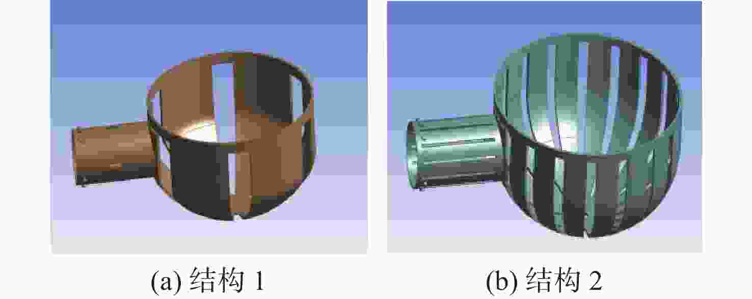
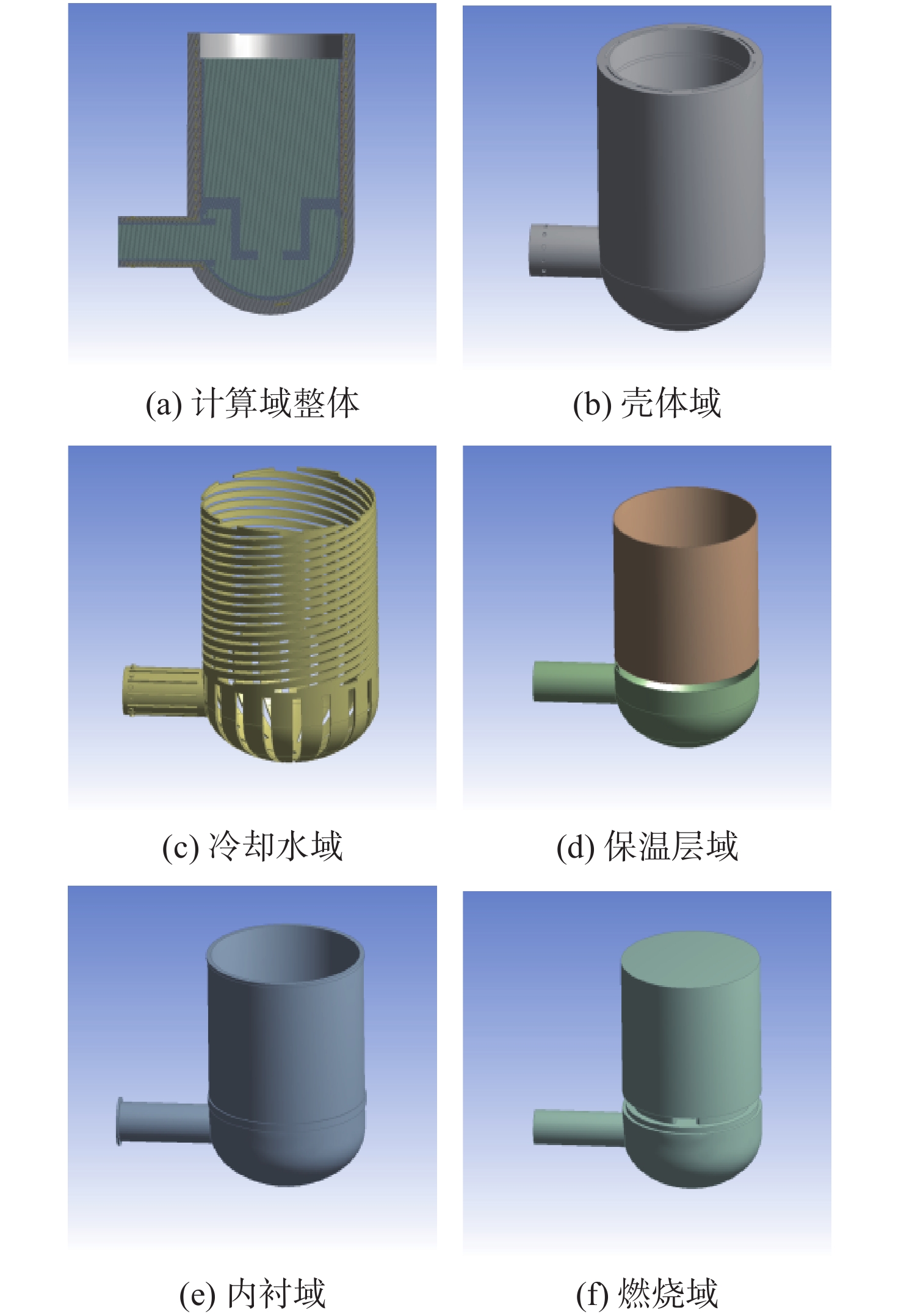
图 2 不同结构冷却水域流道差异
Figure 2. Channel differences of the cooling water area for different structures
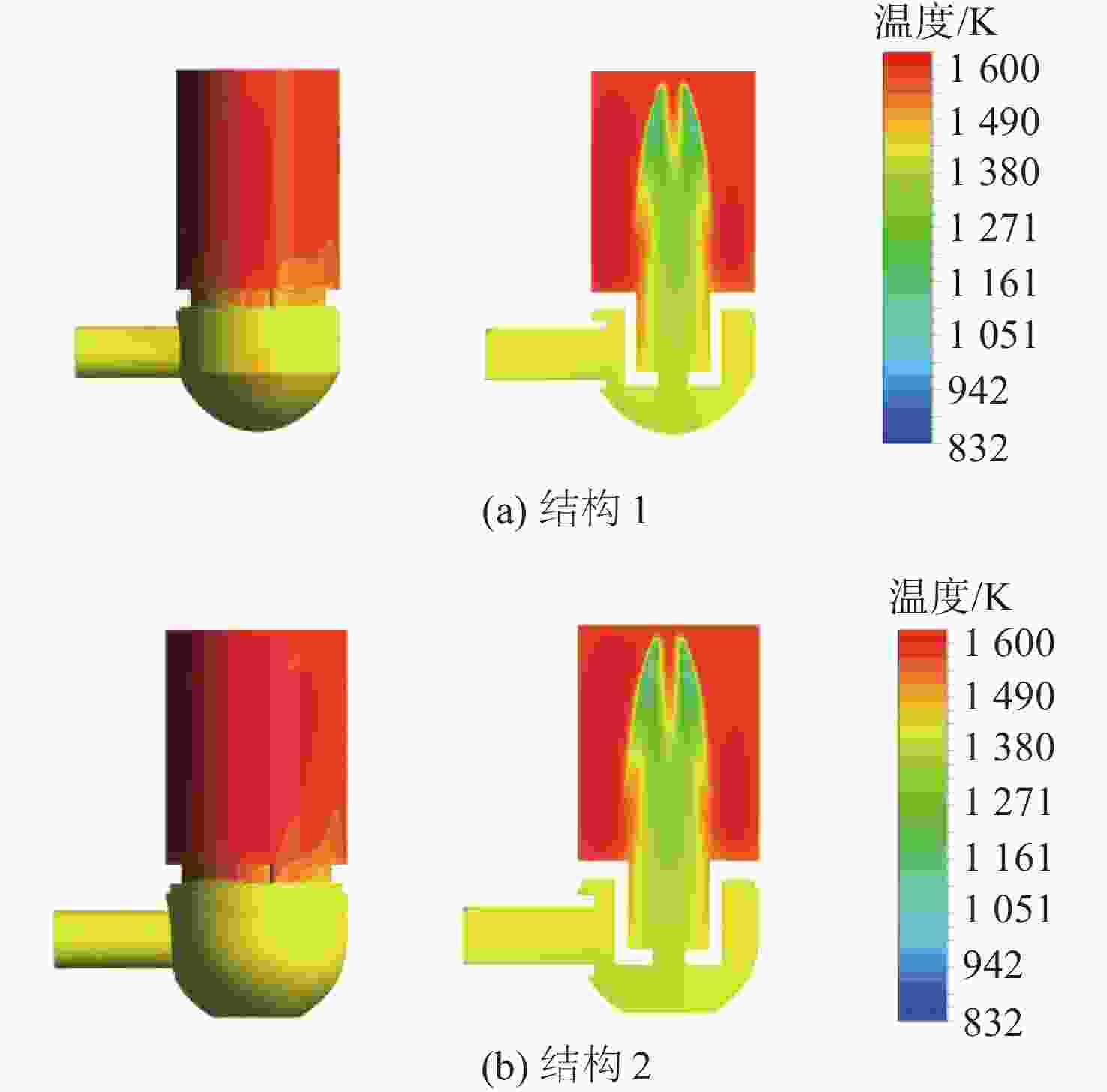
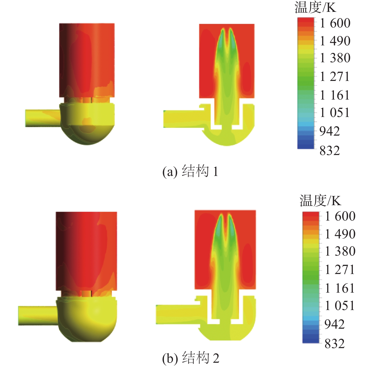
图 5 不同结构燃烧域温度分布云图
Figure 5. Temperature contours of combustion area for different structures
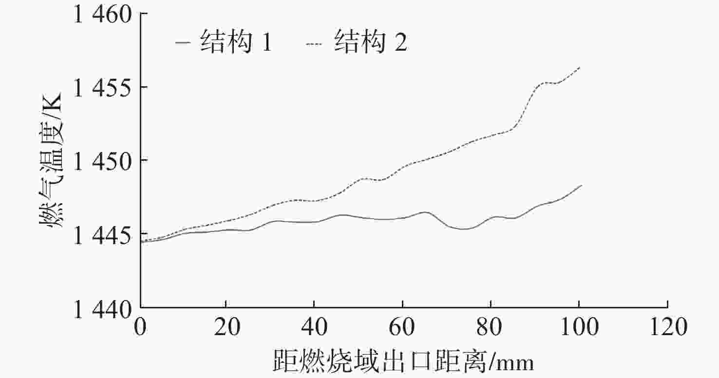
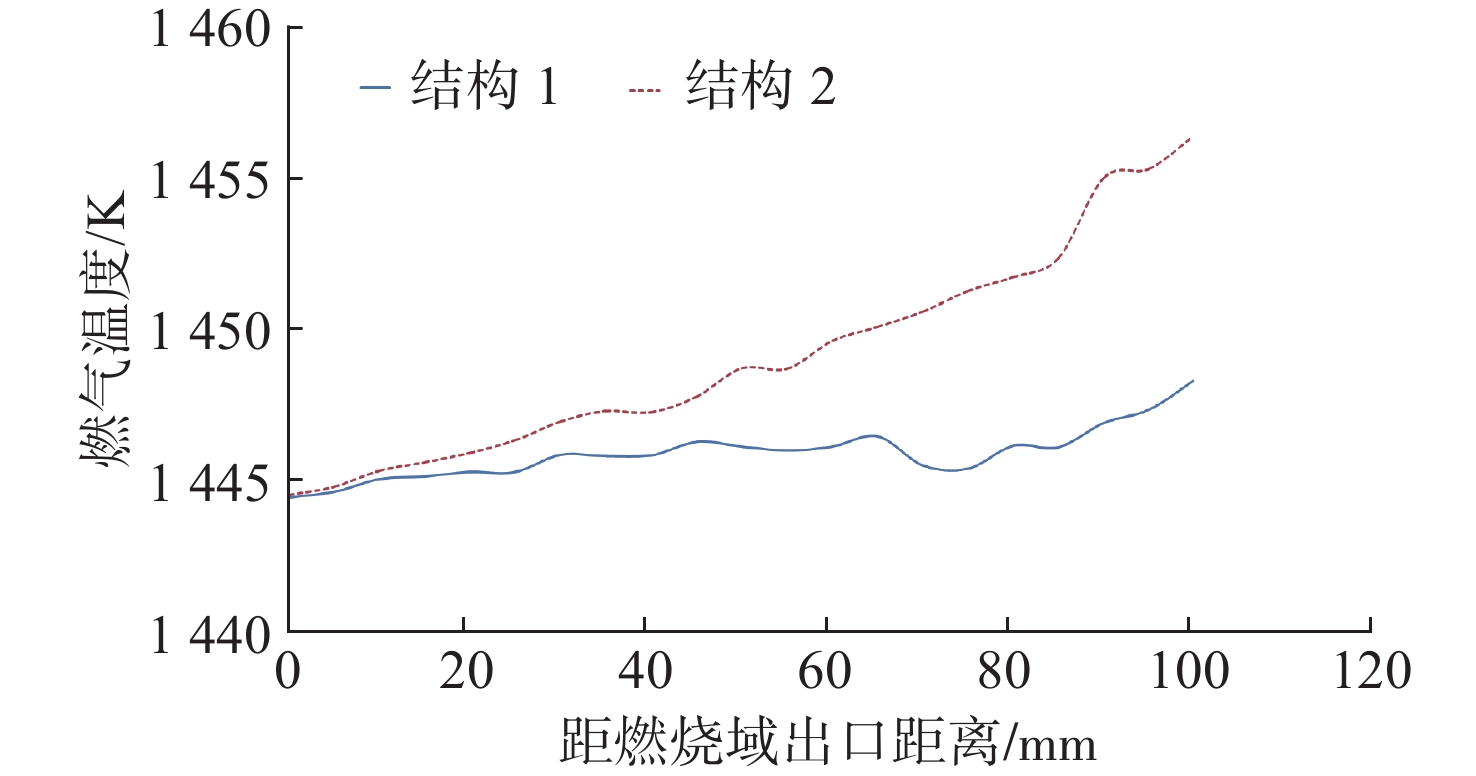
图 6 不同结构燃烧域出口端温度分布曲线
Figure 6. Temperature curves of combustion area in the outlet for different structures
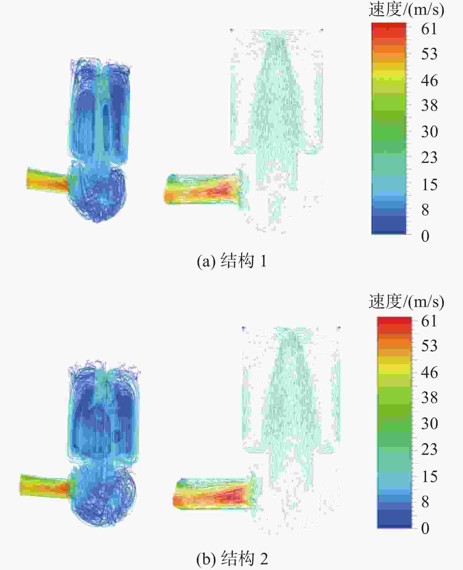
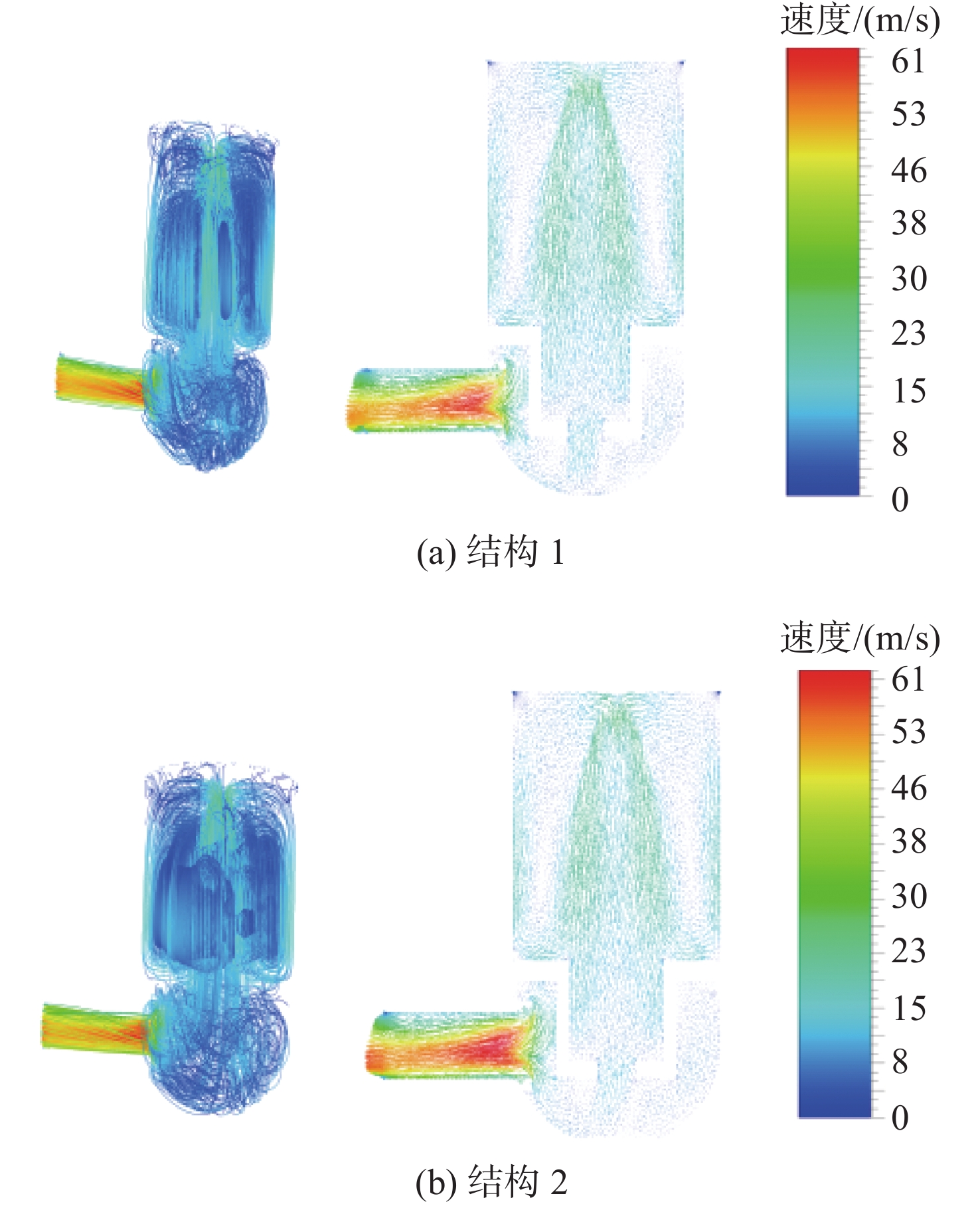
图 7 不同结构燃烧域速度流线图及矢量图
Figure 7. Velocity streamlines and vectors of combustion area for different structures
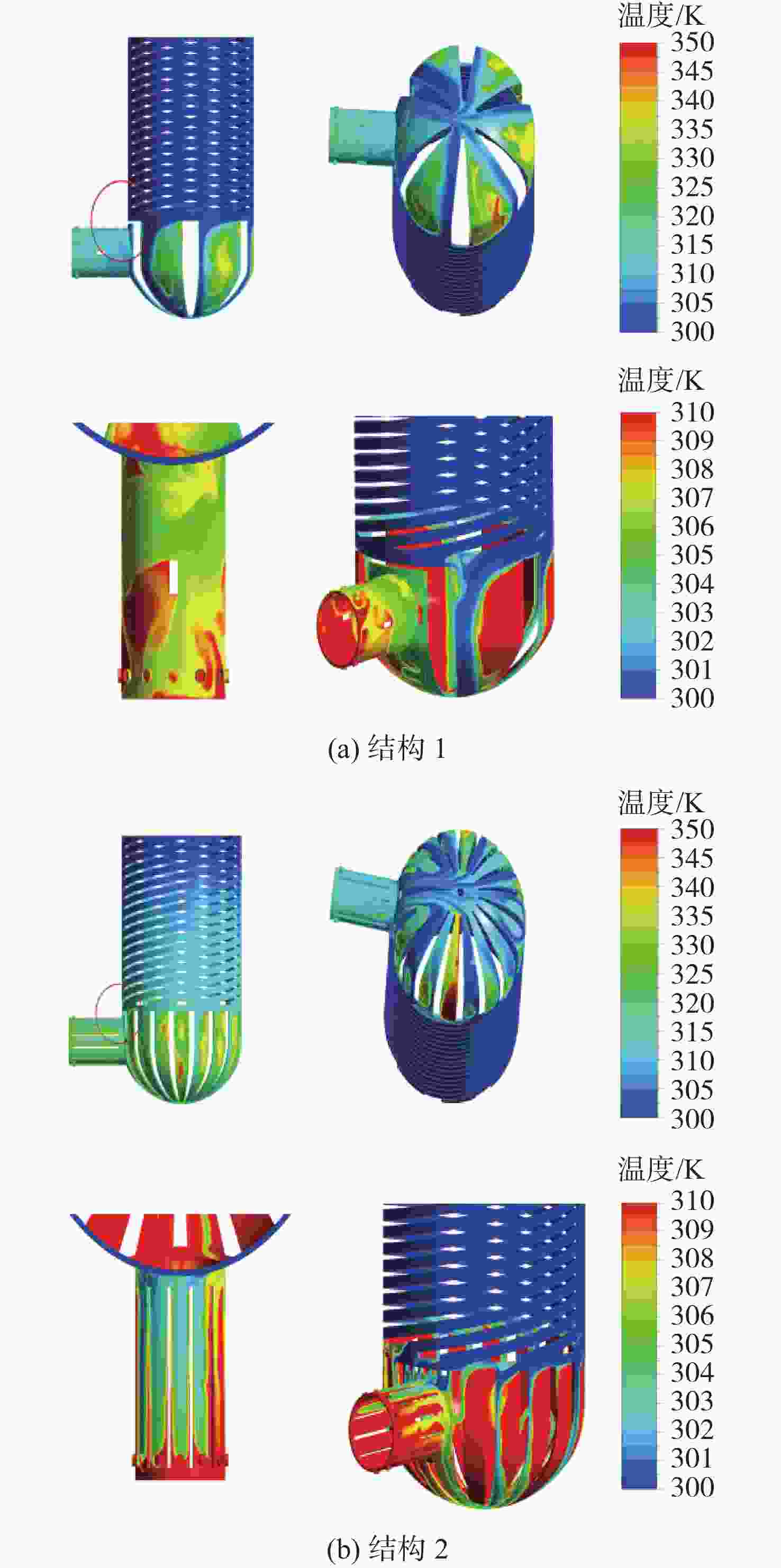
图 8 不同结构冷却水域温度分布云图
Figure 8. Temperature contours of the cooling water area for different structures
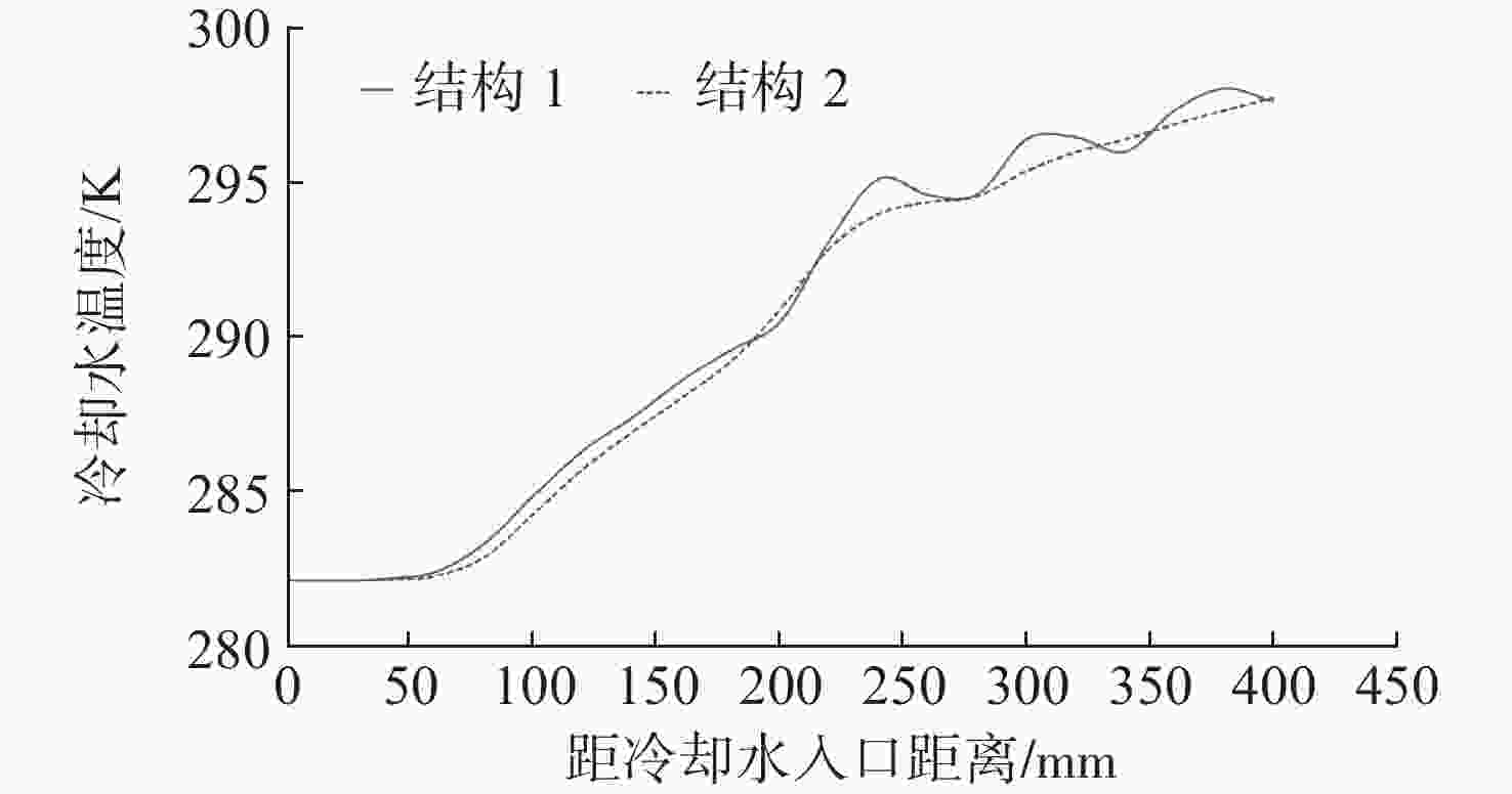
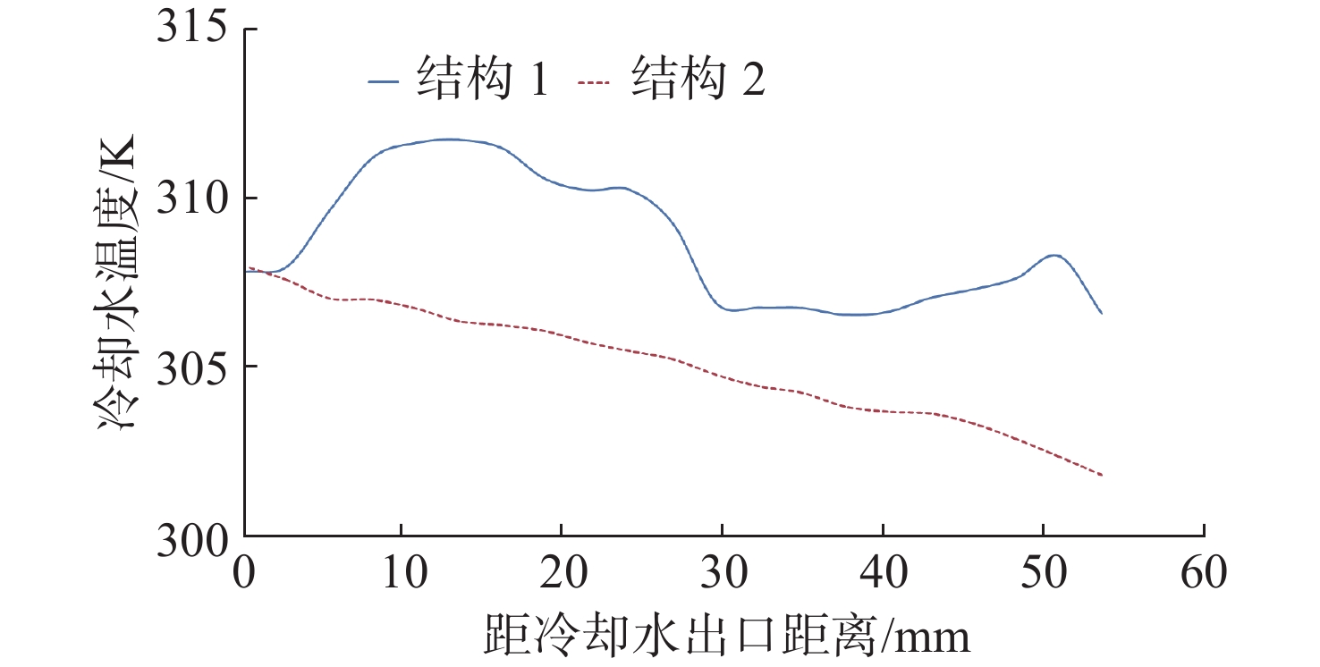
图 9 不同结构冷却水域螺旋流道温度分布曲线
Figure 9. Cooling water temperature curves in the spiral channel for different structures
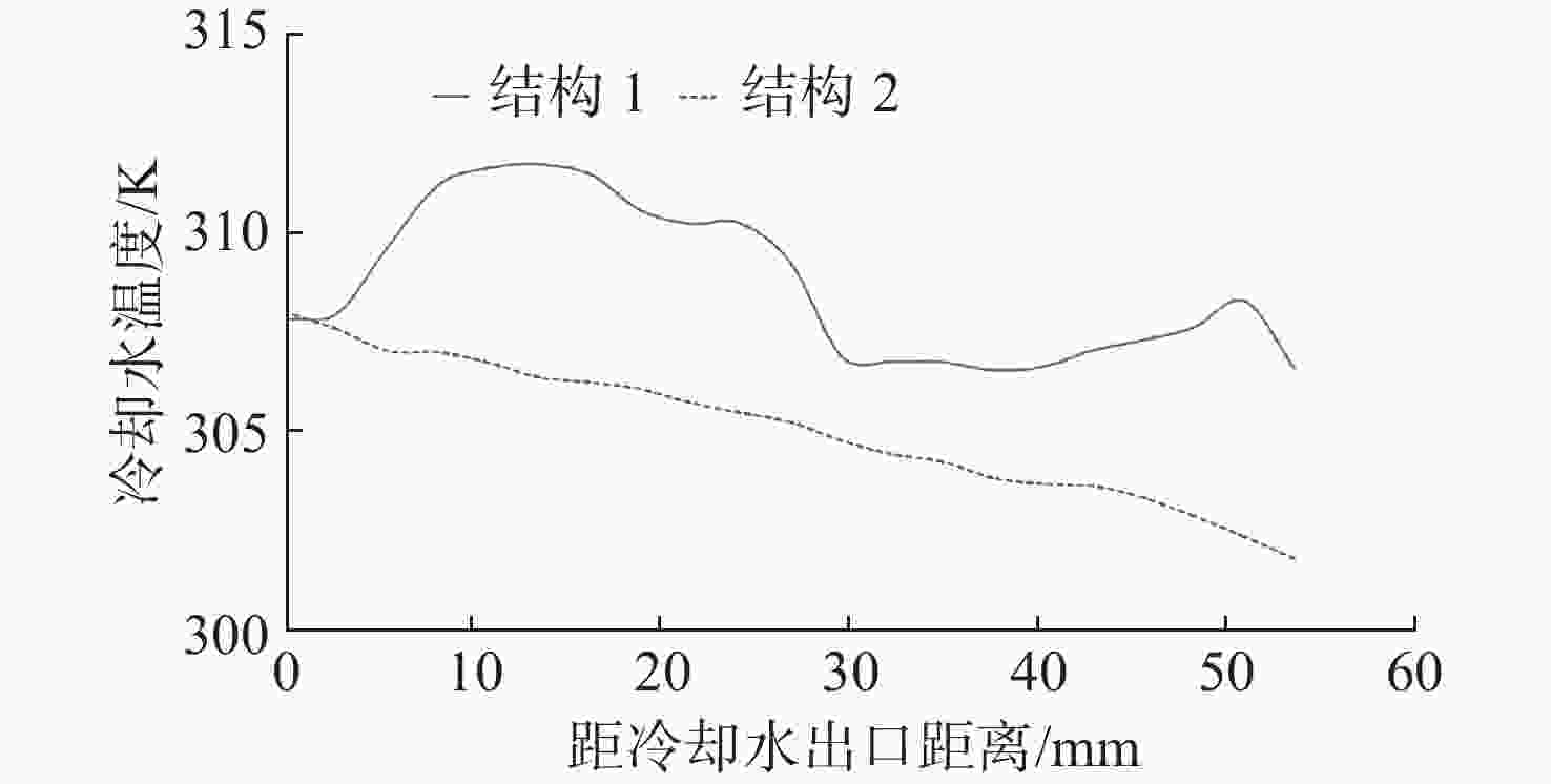
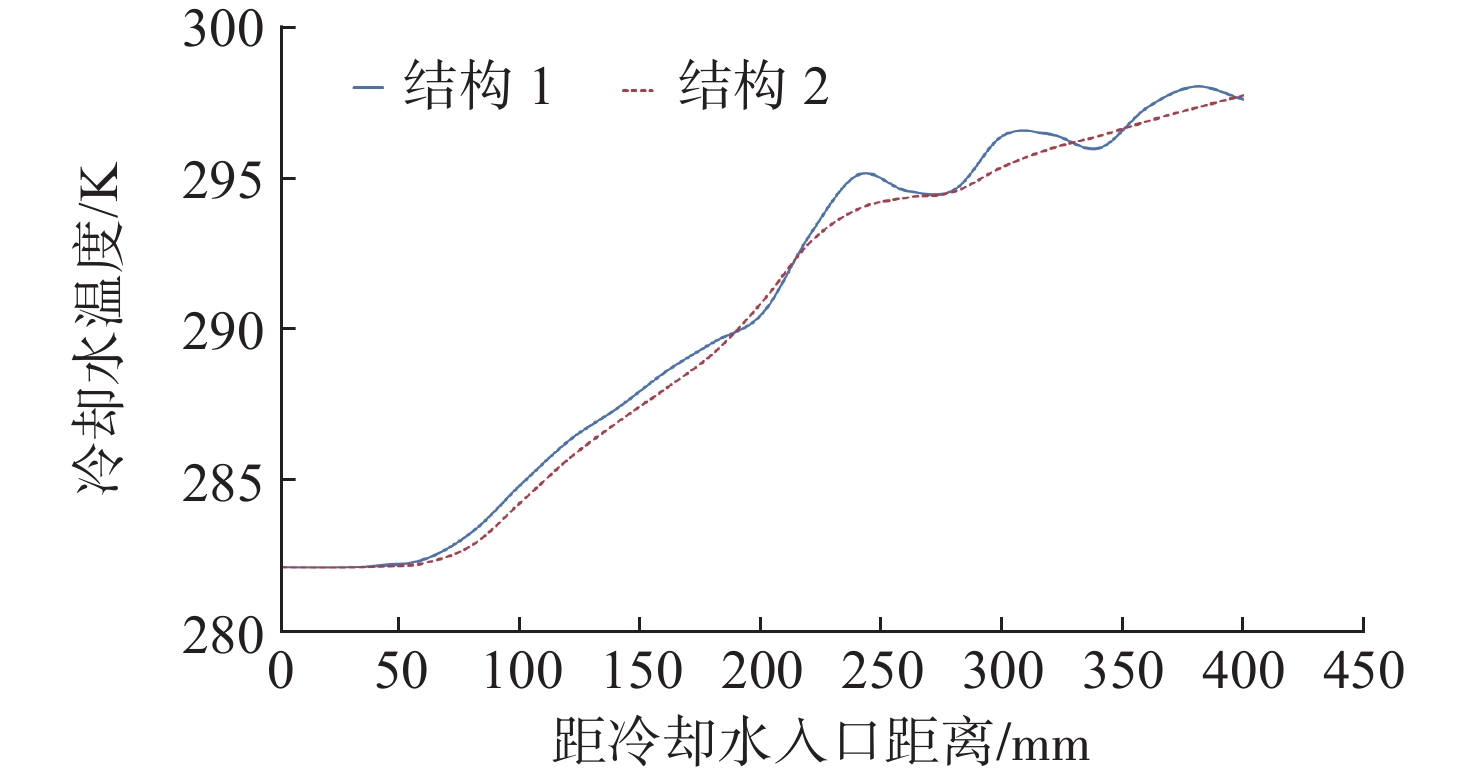
图 10 不同结构冷却水域出口段温度分布曲线
Figure 10. Temperature curves of the cooling water in the outlet area for different structures
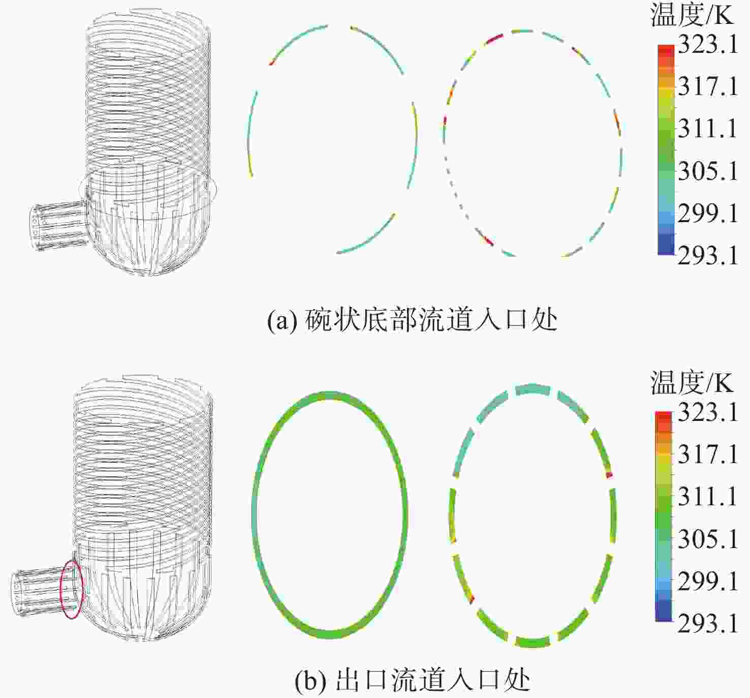
图 11 不同结构差异处冷却水域温度分布云图
Figure 11. Temperature contours of the cooling water area at the differences for different structures
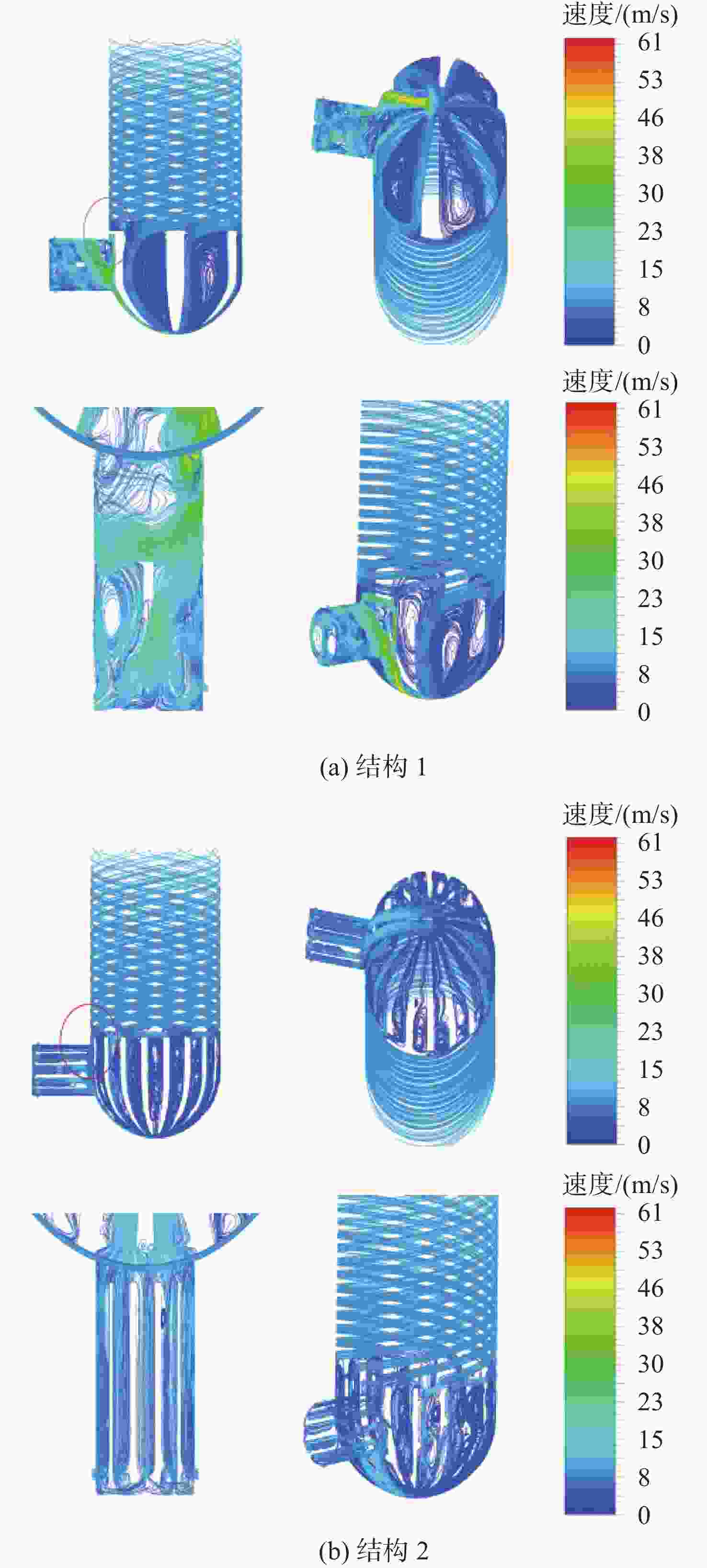
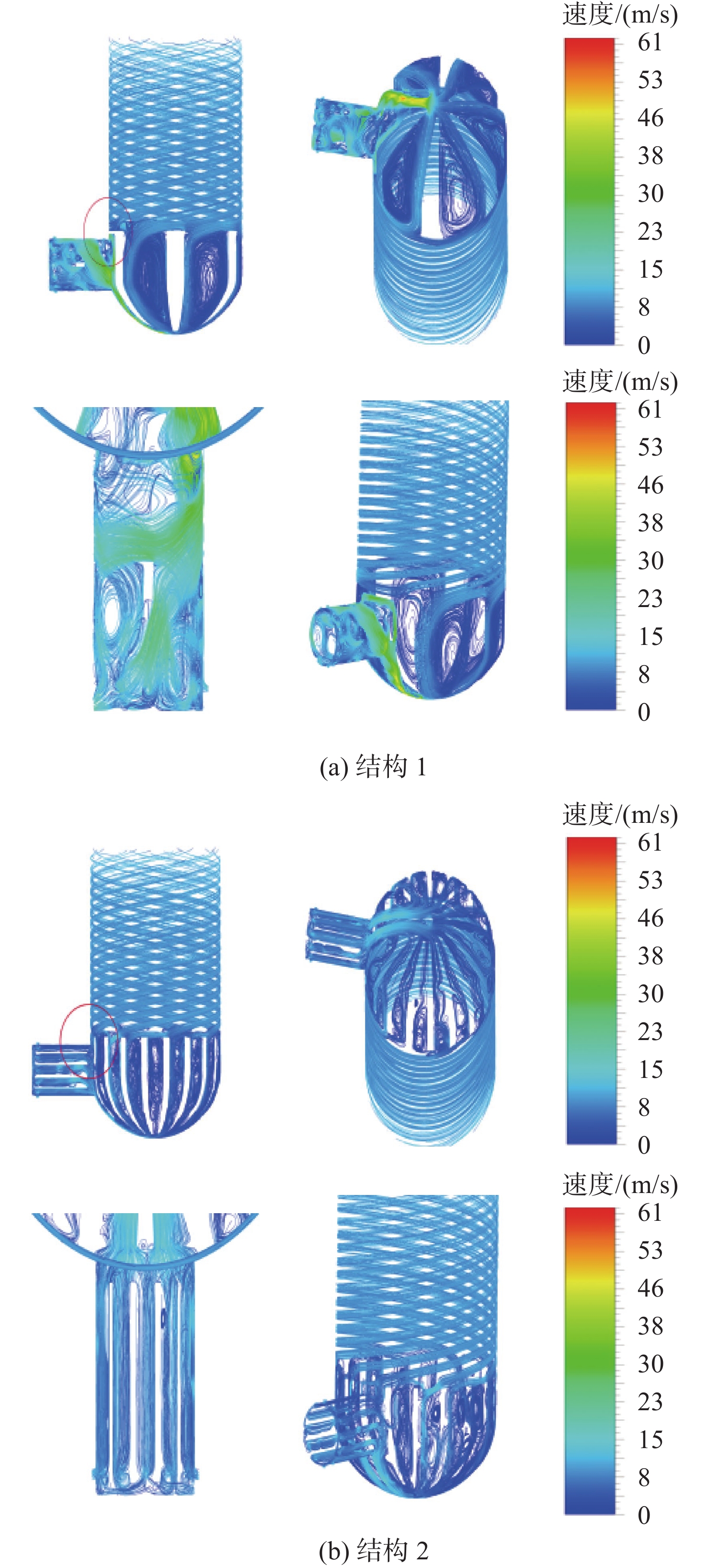
图 12 不同结构冷却水速度流线图
Figure 12. Velocity streamlines of the cooling water area for different structures
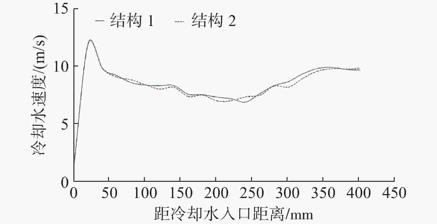
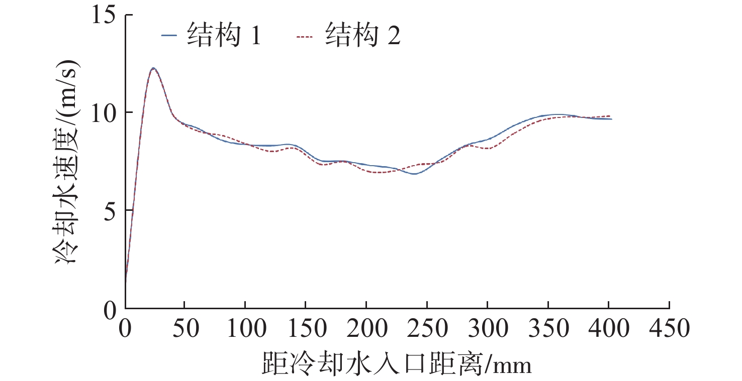
图 13 不同结构螺旋流道水流速度分布曲线
Figure 13. Cooling water velocity curves in the spiral channel for different structures
表 1 不同结构参数对比
Table 1. Parameters comparison for different structures
参数 结构1 结构2 底部流道数/条 6 18 出口流道数/条 1 12 螺旋流道及碗状底部流入
横向出口流道的通道数/条1 10  下载: 导出CSV
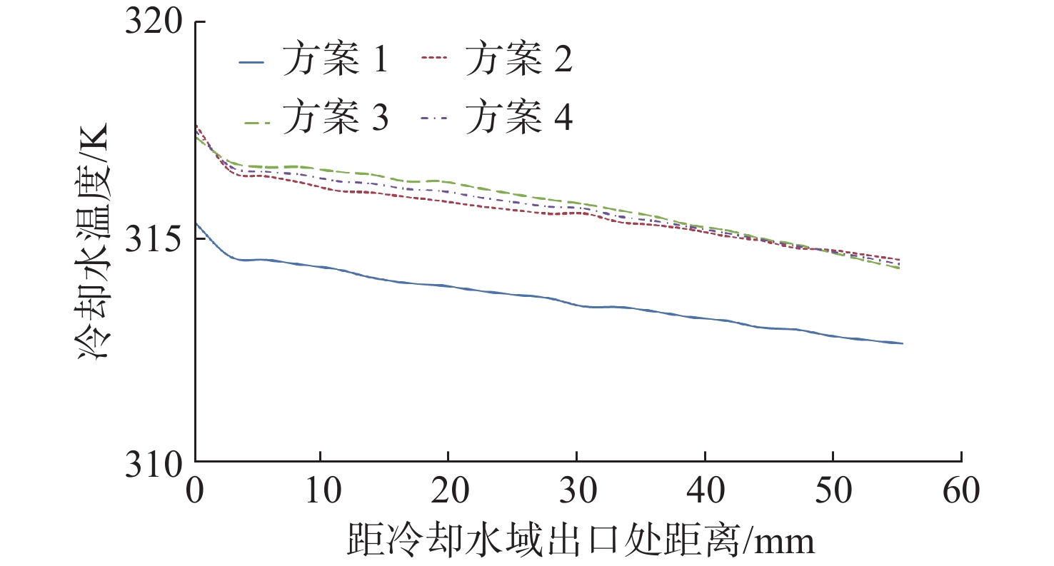
表 2 网格无关性验证网格划分方案
Table 2. Grid division scheme of grid independence verification
参数 方案 1 2 3 4 冷却水域网格尺寸/mm 0.5 0.4 0.340 0.29 燃气域网格尺寸/mm 3.0 3.0 3.000 2.00 网格总数×104 687.0 965.0 1 349 1 770
下载: 导出CSV
表 3 湍流模型选择边界条件设置
Table 3. The boundary condition setting of turbulence model selection
边界条件 参数值 冷却水入口类型 质量流入口 冷却水入口流量/(kg/s) 0.88 冷却水入口温度/K 292.39 冷却水出口类型 压力出口 冷却水出口压力/MPa 0 冷却水出口回流温度/K 320.19 燃料注入温度/K 300.00 燃料液滴直径/mm 0.10 燃料流量/(kg/s) 1.33 燃料喷射半角/(°) 35.00 燃气出口类型 压力出口 燃气出口压力/MPa 20.02 燃气出口回流温度/K 1354.75 计算域网格交界面类型 Coupled Wall
下载: 导出CSV
表 4 不同湍流模型仿真与结果
Table 4. Simulation and experiment results of different turbulence models
参数 模型 试验
结果$ k{\text{-}}\varepsilon $ RNG $ k{\text{-}}\varepsilon $ 可实现$ k{\text{-}}\varepsilon $ 冷却水
出口温度/K317.91 315.27 318.44 320.19 冷却水
出口温升/K25.52 22.88 26.05 27.80 冷却水温升相对
误差/%8.20 17.70 6.31 − 燃气
出口温度/K1 371.65 1 373.18 1 371.24 1 354.75 燃气温度
相对误差/%1.25 1.36 1.22 −
下载: 导出CSV
表 5 不同工况下仿真与试验结果对比
Table 5. Results comparation between the simulation and experiment on the different working conditions
参数 阶段 低工况 中工况 高工况 冷却水
温升/K仿真 14.31 16.48 27.00 试验 13.64 15.94 26.48 相对误差/% 4.91 3.39 1.96 燃气出口温度/K 仿真 1 376.87 1 337.68 1 404.70 试验 1 398.15 1 353.55 1 418.25 相对误差/% 1.52 1.17 0.96
下载: 导出CSV
表 6 除结构差异外其余边界条件设置
Table 6. The other boundary condition setting except the structural difference
边界条件 参数值 冷却水入口类型 质量流入口 冷却水入口流量/(kg/s) 0.823 冷却水入口温度/K 282.110 冷却水出口类型 压力出口 冷却水出口压力/(MPa) 0 燃料注入温度/K 300.000 燃料液滴直径/mm 0.100 燃料流量/(kg/s) 1.230 燃料喷射半角/(°) 35.000 燃烧室出口类型 压力出口 燃烧室出口压力/(MPa) 21.530 交界面类型 Coupled Wall
下载: 导出CSV
表 7 不同结构仿真结果对比
Table 7. The comparison of simulation results for different structures
参数 结构1 结构2 冷却水出口温度/K 309.1 311.4 燃气出口温度/K 1404.7 1396.9 冷却水温升/K 27.0 29.3 壳体内表面均温/K 473.8 470.2 壳体内表面最高温/K 948.0 937.0
下载: 导出CSV
表 8 不同结构差异处温度值
Table 8. The temperatures at the differences for different structures
参数 结构1 结构2 碗状底部流道入口处温度/K 301.8 302.1 出口流道入口处温度/K 307.6 309.5 冷却水域出口处温度/K 309.1 311.4 碗状底部流道段温度变化值/K 5.8 7.4 出口流道段温度变化值/K 1.5 1.9
下载: 导出CSV
-
[1] 石秀华, 王晓娟. 水中兵器概论(鱼雷分册)[M]. 西安: 西北工业大学出版社, 2005. [2] 查志武, 史小锋. 鱼雷热动力技术[M]. 北京: 国防工业出版社, 2006. [3] 赵寅生. 鱼雷涡轮机原理[M]. 西安: 西北工业大学出版社, 2001. [4] 刘学, 杨海威, 周伟星. 燃烧室内壁面发汗冷却数值模拟研究[J]. 火箭推进, 2021, 47(4): 30-36. doi: 10.3969/j.issn.1672-9374.2021.04.005Liu Xue, Yang Haiwei, Zhou Weixing. Numerical simulation research on transpiration cooling on the inner wall of combustion chamber[J]. Journal of Rocket Propulsion, 2021, 47(4): 30-36. doi: 10.3969/j.issn.1672-9374.2021.04.005 [5] Chen Z X, Swaminathan N, Mazur M, et al. Numerical investigation of azimuthal thermoacoustic instability in a gas turbine model combustor[J]. Fuel, 2023, 339: 127405. [6] Laurent G, Vincent R, Arnaud M. Lagrangian modelling of turbulent spray combustion under liquid rocket engine conditions[J]. Acta Astronautica, 2014, 94(1): 184-197. [7] Zhukov V P, Suslov D I. Measurements and modelling of wall heat fluxes in rocket combustion chamber with porous injector head[J]. Aerospace Science & Technology, 2016, 48: 67-74. [8] 赵卫兵, 史小锋, 张忠义. 鱼雷燃烧室低频不稳定燃烧分析[J]. 舰船科学技术, 2003, 25(3): 12-15.Zhao Weibing, Shi Xiaofeng, Zhang Zhongyi. An analysis of low frequency combustion instability in torpedo combustor[J]. Ship Science and Technology, 2003, 25(3): 12-15. [9] 赵卫兵, 钱志博, 何长富, 等. HAP三组元推进剂鱼雷旋转燃烧室内流场数值模拟[J]. 鱼雷技术, 2008, 16(3): 40-44.Zhao Weibing, Qian Zhibo, He Changfu, et al. Numerical simulation on turbulent flow in rotary combustion chamber for hap tri-propellant of thermal torpedo[J]. Torpedo Technology, 2008, 16(3): 40-44. [10] Qin K, Wang H, Wang X, et al. Thermodynamic and experimental investigation of a metal fuelled steam Rankine cycle for Unmanned Underwater Vehicles[J]. Energy Conversion and Management, 2020, 223(11): 1-10. [11] 庄逢辰. 液体火箭发动机喷雾燃烧的理论、模型及应用[M]. 长沙: 国防科技大学出版社, 1995. [12] Shafrovich E, Diakov V, Varma A. Combustion of novel chemical mixtures for hydrogen generation[J]. Combustion and Flame, 2006, 144: 415-418. doi: 10.1016/j.combustflame.2005.07.018 -


 点击查看大图
计量
- 文章访问数: 100
- HTML全文浏览量: 20
- PDF下载量: 23
- 被引次数: 0